USB Radio (http://sourceforge.net/projects/usb-radio/)
by Peter Mueller, 

Introduction
Hardware
Scope Images
Software
Target Software
Mac User Interface
Linux User Interface
Windows Interface
Known Issues and Limitations
Bibliography
IntroductionThe project here develops a matchbox size FM radio for the USB port. When I started the project no USB radio was available on the market. This has changed now. Nevertheless it’s still fun and I learned a lot about software development under Mac OS X and MSP430. Be aware that many features are still missing. So far a simple but functional Mac OS X interface is available.Depending on the public interest I plan to provide a construction kit. If you are interested just send me an e-mail. If you are not interested in the radio part of the project it is still very useful as a platform for your own experiments with a modern low power uC. Everything you need is available for free (or really cheap). And you can connect the uC to USB. This may be important because most modern computers do not have a serial port anymore. HardwareHeart of the project is a radio module (OM5610) that is sold by Flextronics and is based on a the Phillips chip TEA5757. The module can be controlled via a three wire serial interface that is connected to a MSP430. No cheap controller I know supports USB out of the box. Either a lot of software has to be written or a more expensive controller is required (not to forget that one has to find a distributor that sells single pieces). Therefore FTDI's FT232BM USB to serial converter is
used in
combination of a
general purpose uC. In Germany both chips are available from
distibutors such as "Reichelt Elektonik". FTDI's FT232BM USB to serial converter is
used in
combination of a
general purpose uC. In Germany both chips are available from
distibutors such as "Reichelt Elektonik". |
Latest News:  [2005-03-05] At the moment I'm
looking for an easy solution to get RDS data out of the radio. So
far I found two chips: SAA6588T
and TDA7330.
The first one handles RDS
data decoding on chip but seems to be rather expensive (~7€). The
second one is cheaper (~1.70€) but requires more complex software. [2005-03-05] At the moment I'm
looking for an easy solution to get RDS data out of the radio. So
far I found two chips: SAA6588T
and TDA7330.
The first one handles RDS
data decoding on chip but seems to be rather expensive (~7€). The
second one is cheaper (~1.70€) but requires more complex software.Please send me a mail if:
[2005-03-04] Just two mail requests
since
project
start (Hi Andreas,
Hi Lars-Olof!).
Maybe I should have started with something else to get famous :-) |
ZTerm for
first
experiments.
The following block
diagram shows the basic building blocks.
Figure 1:
Blockcircuit
of the USB Radio. The heart of the circuit is the OM5610 radio module
from Flextronics.
For prototyping purposes a MSP430 board from
Oliplex was
used. The step-up
converter and the radio module are located on this board. The radio
module needs both a 3.3V and 12V power supply. Because USB only
provides 5V a step-up converter is used to generate the 12V. The
converter is realized using the MC34063A
from
Motorola. It is cheap and
needs only few external parts. The desin is a standard design as
described in the datasheet. See mc34063a
devaid for a simple-minded design
tool that allows you to calculate component values. The following
values were used: Ct=33Pf, Rsc=11Ohm, L=2.2mH, R=180Ohm, R1=1.5k,
R2=11k.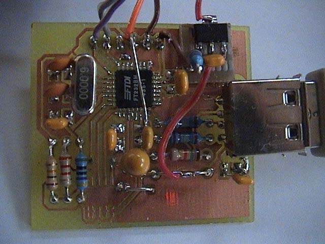 Figure 2a: USB to RS232 converter. In principle one could use a commercial USB2Serial cable, but then the radio would need a separate power supply. |
 Figure 2b: Controller board with step-up converter and radio module. |
The USB to RS232 converter is on a second board. The design follows the proposal on page 23 of the data sheet. The whole circuit is bus-powered. In order to meet the <= 500uA total suspend current requirement (including external logic) a BS171 Mosfet is used as power switch to control the power to external logic circuits such as the radio and the step-up converter. For the 3.3V supply of the radio module and the MSP430 the 3v3Out of the FT232BM chip is used. Current consumtion is below the specified limits (@@@ to be verified).
The connection between the FT232BM Chip and the MSP430 are just the Rx and Tx signals (8N1@9600 Baud). Because the FT232BM is a 5V supplied chip, a voltage devider (91kOhm/xxx) is used to adapt the Tx signal from 5V to 3.3V. The Rx level is just ok for the FT232 to detect a high signal.
A complete circuit diagram can be found
here
and the Eagle scheet 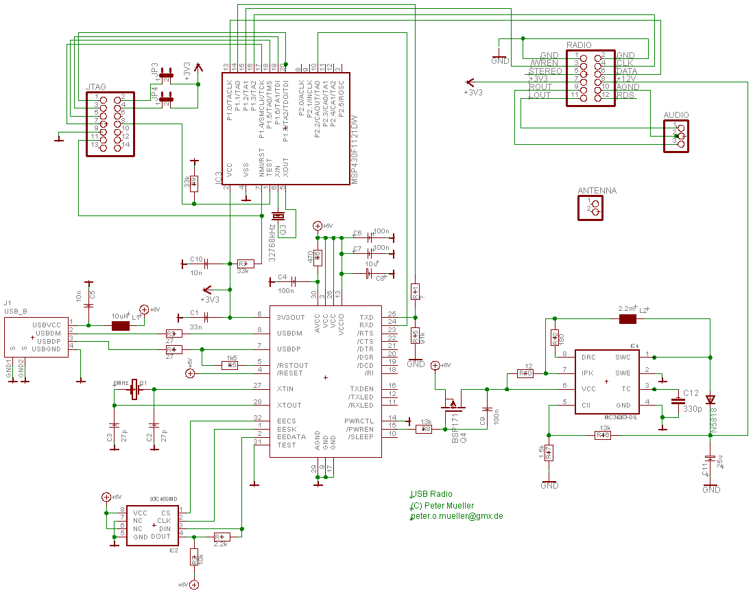 here.
here.Scope Images
The following figures show the startup behaviour of the circuit. After the USB plug was plugged in initialization of the USB slave FT2232BM happens. If it is ready it activates the /PRWEN output that drives the mosfet. The next figures show the delay between plugging in the USB plug and switch-on of the mosfet. Figure 3a: C1 shows the 5V supply. C2 shows the 12V output. |
 Figure 3b: Lab1/1 shows the 5V and Lab1/0 the /PWREN signal that is delayed until the USB controller has initialized the USB device. |
The following few figures show the serial interface signals for certain commands.
 Figure 4a: Setting the station frequency to 93500MHz that corresponds to 0x1870. LAB1/0 is the data line, LAB1/1 /WREN and LAB1/2 clock. |
 Figure 4b: Seek downwards and accept only stations with a signal strength of at least 10uV. LAB1/0 is the data line, LAB1/1 /WREN and LAB1/2 clock. |
Software
Target Software
The software was
developed
with the msp430-gcc tool chain. All the tools can be downloaded
from msp430-gcc. The
software works as a
simple foreground/background
system. Until a character is received the controller waits in low power
mode. If a complete command was detected the corresponding actions are
executed. The following commands are implemented so far:- seeku n seek the next station upwards where n specifies the required signal strength A to D (A lowest to D highest). If the next station was found its frequency is printed.
- seekd n seek the next station downwards where n specifies the required signal strength A to D (A lowest to D highest). If the next station was found its frequency is printed.
- read reads and displays the currently active station.
- readr n reads and displays the
current content of the shift register of the TEA5757 chip. This command
is mainly useful for debugging.
- radio s sets a new station whereas s is the station frequency devided by 50. This makes is possible to just use integer arithmetic in the MSP430 device.
Mac User Interface
An application for Mac OS X is just under develoment. The current state can be viewed in SF's CVSrepository.
Figure 5: Configuration window to predefine stations. These stations can be directly chosen in the main menu (see figure 6).

Figure 6: Main menue.
For the Mac software a review of an experienced developer could improve code quality and look and feel a lot. This is my first software project on Mac OS X!
Windows Software
TBDLinux Software
TBDKnown Issues and Limitations
- The seek up and down command should print the latest
station if radio has locked. This does not work as expected. The
software detects that the radio has locked before it is actually
locked. As a result a wrong frequency is returned.
- From time to time weak stations are lost. Not sure what the problem is. Maybe the noise on the 12V supply for the radio module's tuning diodes is too high
- Only the frequency of the selected station is available. There is no RDS signal decoding implemented (and probably will never because it requires an additional chip).
- Improve Mac Software to allow scheduled recording of the radio signal
- Scheduled power on before a broadcast starts and shut down after the broadcast finished
- Installer missing
- Develop Windows and Linux HMI
Bibliography
| [mc34063a] | ON Seminiconductor, http://onsemi.com |
| [msp430-gcc] | http://mspgcc.sourceforge.net/ |
| [olimex] |
http://www.olimex.com |
| [FTDI] |
http://www.ftdichip.com/ |
| [ZTerm] |
http://homepage.mac.com/dalverson/zterm/ |
| [mc34063a devaid] |
http://www.nomad.ee/micros/mc34063a/index.shtml |
Last Change 2005-01-15